
E-mail: ncjt@zjncjt.com


Content
A refinery must keep a sulfur transfer line above its melting point along a 400-meter pipe rack where no steam supply exists. A chemical plant must hold a polymer line at a stable 200°C through winter. In both cases, hot oil tracing delivers uniform, controllable heat without the condensate handling of steam or the electrical load of resistance tracing.
Consider hot oil tracing when a site already operates a thermal oil heating system, or when process temperatures must stay within a narrow window between roughly 150°C and 350°C. It is not the simplest option for short runs or isolated lines; electric tracing is usually easier there. But for long process piping, multiple parallel lines, or areas where steam pressure is unreliable, hot oil tracing often wins on both energy efficiency and temperature control.
A hot oil tracer is a smaller-bore tube, usually 12–20 mm in diameter, running along the process pipe between a supply header and a return header. Hot thermal oil circulates continuously through the tracer. Heat passes through the tracer wall into the contact surface or the small air gap between tracer and process pipe, and an outer layer of insulation traps that heat so it travels inward to the process fluid rather than escaping to the atmosphere.
The engineering logic differs from steam in one fundamental way. Steam releases latent heat as it condenses, so a steam tracer delivers a large, fixed amount of energy at a constant temperature. Hot oil operates entirely with sensible heat. No phase change occurs, so every watt of heat transferred comes from the temperature difference between the oil and the process line. The design temperature drop across the traced section, together with the oil flow rate, sets the heating capacity.
Two piping arrangements are common. In the first, the supply header feeds a single tracer along the process line and the tracer discharges to the return header. In the second, the same oil passes the traced section twice: out along one tracer and back along a second before returning to the header system. The two-line arrangement nearly doubles the heat-transfer surface and suits long lines or high heat requirements. Large installations are often split into 50-meter sections, each with its own pressure drop and return connection, to simplify balancing and troubleshooting.
Steam tracing dominates because steam is often already available at the plant and delivers more heat per meter than hot oil or electric cable. The trade-off is infrastructure: steam traps, condensate return, and careful insulation to prevent freezing. Steam temperature is tied to supply pressure, so keeping a heat-sensitive product at 180°C requires pressure-reducing stations or additional control valves.
Electric tracing offers the cleanest installation: no circulating fluid, no leaks, no phase change, and precise control. Its main drawbacks are the operating cost per kilowatt, limited electrical capacity in older plants, and the care needed to design long circuits so that voltage drop and cold-lead terminations do not create hotspots or underpowered sections.
Hot oil tracing sits between the two. It uses organic heat-transfer fluids, typically synthetic or mineral oils, and gives the plant a closed liquid circuit with no condensate handling. It holds a stable temperature across the traced length because the oil temperature is controlled centrally at the heater. It shares the sensible-heat limitation: the oil must keep flowing, and the temperature drop from inlet to outlet must stay within the allowable process window.
| Criterion | Hot oil tracing | Steam tracing | Electric tracing |
|---|---|---|---|
| Heat transfer mechanism | Sensible heat of circulating thermal oil | Latent heat of condensing steam | Resistive heating of a conductive element |
| Typical temperature range | 150–350°C by oil grade | 100–200°C by steam pressure | From frost protection to over 400°C |
| Temperature control | Central heater setpoint, uniform along the line | Tied to steam pressure, needs conditioning | Per-circuit controllers, local and precise |
| Infrastructure | Oil heater, expansion tank, supply and return headers | Steam supply, traps, condensate return | Power distribution, control panels, terminations |
The number of tracers and how they contact the pipe determine how much heat reaches the product. A single tracer clamped to the top of a horizontal pipe transfers less heat than two tracers run along the lower quadrants, where liquid product sits. For high-duty services, multiple tracers with heat-transfer compound improve contact. Never rely on a tracer simply strapped to the pipe; air is a poor conductor, and the gap can cut delivered heat dramatically.
Design starts from the heat loss of the insulated pipe at the lowest ambient temperature, not from the product temperature alone. Once the heat loss is known, the oil flow rate is set so that the temperature drop along the traced section stays small, normally 10–30°C for a well-balanced system. If the oil cools too much, the far end cannot hold the product temperature. Flow balancing is essential; 50-meter or longer sections should each have measurable flow control or at least a positive return-line indication.
Every heat-transfer fluid has a maximum bulk temperature and a maximum film temperature. Running the heater too close to the film limit causes cracking, coking, and carbon deposits inside the tracer that silently reduce heat transfer. Once the film fouls, capacity falls year by year, and raising the oil temperature only accelerates the deposits. Select an oil whose bulk temperature rating is at least 30–50°C above the required tracing temperature, and monitor oil analysis on a scheduled basis.
The insulation layer is part of the heat-transfer calculation, not an afterthought. Thickness must suit the tracer temperature and the ambient conditions. The material must tolerate the highest possible oil temperature, not just the normal process temperature, because a failed controller can send the tracer above its operating point. The installation must be tight: gaps, sagging sections, and crushed insulation at hangers create cold spots that bleed heat exactly where the pipe needs it most.
For traced lines above 250°C, conventional mineral wool and elastomeric foams are inadequate. Low thermal conductivity, dimensional stability, and freedom from organic content are the three criteria that matter most. Ceramic fiber products retain their insulating performance at these temperatures while remaining easy to fit and cut, which is why the same material family used in high-temperature furnace linings also insulates traced piping.
A ceramic fiber blanket insulation is the most practical choice for straight sections of traced pipe because it wraps tightly, compresses to fill small irregularities around the tracer, and can be double-layered with staggered joints. At valves, flanges, and instrument tees, where the tracer forms tight bends and insulation must fill irregular voids, ceramic fiber cotton provides the resilient fill that prevents air pockets.
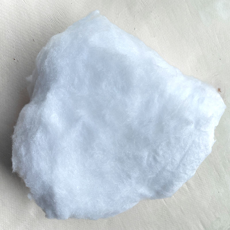 Ceramic Fiber Cotton Manufacturers, Factory - Zhejiang Nengcheng Crystal Fiber CNengcheng is China Ceramic Fiber Cotton Manufacturers and Factory, Custom Ceramic Fiber Cotton for sale, IntroductionNC ceramic fiber cot...View Product →
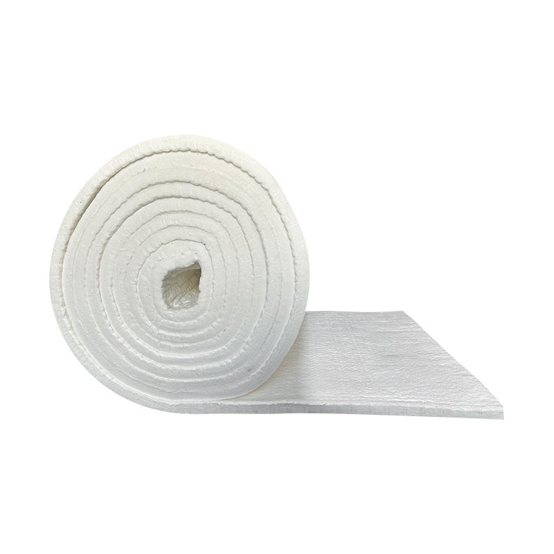 Ceramic Fiber Blankets Manufacturers, Factory - Zhejiang Nengcheng Crystal FiberNengcheng is China Ceramic Fiber Blankets Manufacturers and Factory, Custom Ceramic Fiber Blankets for sale, Introduction The NC ceramic ...View Product →
A common field mistake is to insulate the process pipe first and let the tracer sit outside the insulation. That defeats the purpose: the tracer heats the insulation instead of the pipe. The correct sequence is tracer against the process wall, insulation over both, then a weatherproof jacketing layer. The insulation must also keep its outer surface below a safe touch temperature.
Our high-temperature thermal insulation materials buyer's guide covers temperature grades, conductivity, and installation detail that affect traced-line performance.
Hot oil tracing problems repeat across industries. Recognizing them early prevents shutdowns.
The same discipline applies to electric and steam tracing, which is why many plants standardize tracing procedures. For broader guidance on thermal insulation materials for industrial heating systems, document the choice for each traced line and review it whenever the process temperature changes.
Hot oil tracing is not the default choice for every pipeline. If steam is plentiful and the product tolerates its temperature, steam tracing is simpler. If the line is short and electricity is cheap, electric tracing is cleaner. Hot oil tracing earns its place when temperatures must be uniform and controllable in the 150–350°C range, when a thermal oil plant already exists, or when steam is unavailable and power capacity is limited. For long pipe racks with many parallel traced lines, one central heater and two headers serve the entire rack without hundreds of steam traps or dozens of electric circuits.
The final design rule is to treat the oil circuit and the insulation layer as one system. The oil delivers heat; the insulation decides where that heat goes. Trace tight against the pipe, insulate immediately, keep the insulation dry, and balance every section's return temperature. Our technical support team can help with material selection and traced-line insulation reviews.
Introduction: Aluminum silicate fiberboard material is currently a high-performance insulation material. Aluminum silicate fiberboard has excellent properties such as light w...
Introduction: Aluminum silicate refractory fiber products are made by selective processing of pyroxene, high-temperature melting, blow molding into fibers, solidification mol...
Introduction: 1、 Shaped ceramic fiber furnace lining for high alumina ceramic fiber board The shaped ceramic fiber furnace lining of high alumina ceramic fiber board mai...

An enterprise integrating design, R&D, production, sales and engineering services. Ceramic Fiber Board Manufacturers, Vacuum Heat Treatment Solutions in China
Phone: +86-13967261180
+86-17858398898
Email: ncjt@zjncjt.com
Arlen@zjncjt.com
Tel: +86-572-8295956
Add: Wulintou, Tangbei Village, Leidian Town, Deqing Country, Huzhou City, Zhejiang Province, China
Copyright © 2024 Zhejiang Nengcheng Crystal Fiber Co., Ltd. All Rights Reserved.

 English
 Español
 عربى
عربى