E-mail: ncjt@zjncjt.com


At temperatures above 1000°C, the insulation surrounding a furnace tube is not a passive component — it is an active part of the thermal system. Choose wrong, and heat bleeds through the wall, energy costs climb, and tube replacements come too often. Ceramic fiber tubes offer a different answer: purpose-built for high-temperature furnace environments, they combine low thermal mass, strong thermal shock resistance, and chemical stability in a single, lightweight form factor.
Content
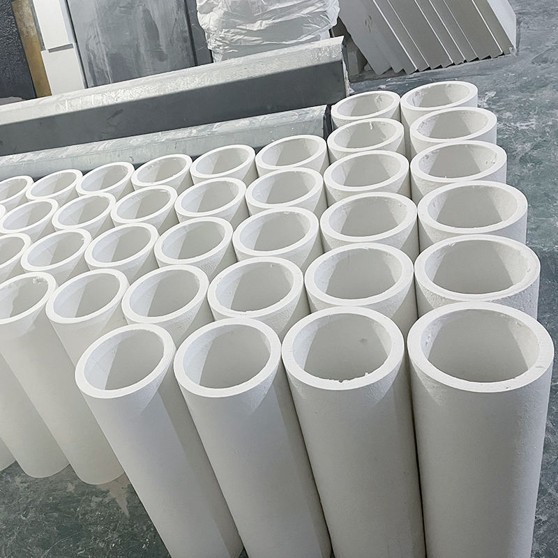
A ceramic fiber tube is a hollow cylindrical product formed from high-purity alumina-silicate or polycrystalline alumina fibers. Unlike cast refractory shapes, which rely on dense crystalline structures for strength, ceramic fiber tubes achieve their performance through a tightly packed fiber matrix — a structure that is inherently resistant to rapid thermal cycling.
The two dominant manufacturing routes are vacuum forming and winding/wrapping. Vacuum-formed tubes are produced by drawing an alumina-silicate fiber slurry onto a mandrel under suction, then drying and firing the shape. This process delivers excellent dimensional consistency and is suited to standard pipe sizes. Wound tubes, by contrast, use fiber paper or blanket wrapped around a mandrel and bonded with a high-temperature binder — a method that allows greater flexibility in wall thickness and length customization.
The case for ceramic fiber tubes in furnace applications rests on several measurable properties that traditional materials simply cannot match simultaneously.
High-temperature resistance. Standard alumina-silicate ceramic fiber tubes operate continuously at 1000°C to 1260°C, while high-alumina and polycrystalline grades extend that ceiling to 1400°C or beyond. The fiber matrix retains structural integrity at these temperatures without sintering into a brittle mass — a failure mode common in calcium silicate and low-grade refractory shapes.
Low thermal conductivity. At 1000°C, thermal conductivity for a typical ceramic fiber tube is in the range of 0.20–0.30 W/m·K — significantly lower than dense refractory brick (often above 1.0 W/m·K) or calcium silicate board. In practice, this means the tube wall itself stores and transmits far less heat, reducing furnace heat loss and improving the efficiency of the thermal process.
Thermal shock resistance. Industrial furnaces rarely operate at steady state for their entire service life. Shutdown cycles, process interruptions, and rapid temperature ramps all impose thermal gradients on insulation components. Ceramic fiber tubes tolerate these cycles without cracking or spalling because the fibrous structure accommodates differential thermal expansion elastically, rather than resisting it rigidly.
Lightweight construction. Ceramic fiber tubes weigh a fraction of equivalent refractory brick or castable sections — typically 200–400 kg/m³ in bulk density, compared to 1800–2200 kg/m³ for dense refractories. For furnace designers, this translates directly into reduced structural load, easier installation, and faster furnace assembly.
Chemical stability. The alumina-silicate composition resists attack from most industrial process gases, including oxidizing and mildly reducing atmospheres. The tubes are also resistant to dilute acids and alkalis, making them suitable in petrochemical reactors, heat treatment atmospheres, and chemical processing furnaces where liner materials are exposed to aggressive environments.
Ceramic fiber tubes serve multiple roles across furnace types and industries. The most common applications include:
Switching from conventional insulation to ceramic fiber tubes is not simply a material substitution — it rebalances the economics of furnace operation. The comparison below covers the most common alternatives.
| Material | Max Temp (°C) | Thermal Conductivity (W/m·K @ 1000°C) | Density (kg/m³) | Thermal Shock Resistance |
|---|---|---|---|---|
| Ceramic Fiber Tube (Al-Si) | 1260 | 0.20–0.30 | 200–400 | Excellent |
| Ceramic Fiber Tube (High Alumina) | 1400+ | 0.25–0.35 | 300–500 | Excellent |
| Calcium Silicate Pipe | ~1000 | 0.18–0.22 | 200–350 | Poor–Moderate |
| Dense Refractory Brick (lined) | 1400+ | 1.0–1.8 | 1800–2200 | Poor |
| Castable Refractory Tube | 1400+ | 0.6–1.2 | 1600–2000 | Moderate |
The thermal conductivity gap between ceramic fiber and dense refractory is the most consequential difference in daily operation. All-fiber furnace linings have been shown in controlled research to reduce fuel consumption by up to 40% compared to hard refractory-lined furnaces operating under identical conditions — a result driven by the material's low heat storage and minimal steady-state conduction losses. For a production furnace running continuously, that efficiency difference compounds into significant cost savings over a year of operation. The full range of ceramic fiber thermal insulation materials available today spans blankets, boards, modules, and shaped forms, each suited to a specific location in the furnace structure.
Getting the specification right before ordering prevents costly replacements and unplanned downtime. Four parameters drive most selection decisions:
Ceramic fiber tubes are significantly more fragile than metal or castable refractory equivalents. A few practical precautions during handling and installation protect the investment and ensure long service life.
Selecting the right ceramic fiber tube — and installing it correctly — is one of the most reliable ways to extend furnace campaign life, reduce maintenance intervals, and lower the energy cost per unit of production. For application-specific guidance on tube grades and configurations, contact the engineering team directly.
Introduction: Aluminum silicate fiberboard material is currently a high-performance insulation material. Aluminum silicate fiberboard has excellent properties such as light w...
Introduction: Aluminum silicate refractory fiber products are made by selective processing of pyroxene, high-temperature melting, blow molding into fibers, solidification mol...
Introduction: 1、 Shaped ceramic fiber furnace lining for high alumina ceramic fiber board The shaped ceramic fiber furnace lining of high alumina ceramic fiber board mai...
An enterprise integrating design, R&D, production, sales and engineering services. Ceramic Fiber Board Manufacturers, Vacuum Heat Treatment Solutions in China
Phone: +86-13967261180
+86-17858398898
Email: ncjt@zjncjt.com
Arlen@zjncjt.com
Tel: +86-572-8295956
Add: Wulintou, Tangbei Village, Leidian Town, Deqing Country, Huzhou City, Zhejiang Province, China
Copyright © 2024 Zhejiang Nengcheng Crystal Fiber Co., Ltd. All Rights Reserved.

 English
 Español
 عربى
عربى